Set Appliance State:
| Isolate Mains Power to appliance as per TOPs P4 |
Set Multimeter to Resistance 
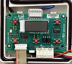
Remove connector CN5 from the display PCB
Measurement:
Measure the resistance between the pins on CN5 and the terminals on the incoming mains terminal block as listed in the table below:
Expect continuity (zero resistance) on each test.
Also visually inspect the harness for general condition and any signs of damaged insulation.
| Connector CN5 | Incoming terminal strip | White | Terminal 1 |
| Yellow | Terminal 3 |
| Black | Terminal 2 |
Expect continuity (zero resistance) on each test.
Also visually inspect the harness for general condition and any signs of damaged insulation.


Isolate as per TOPs P4
and refit as necessary