Set Appliance State:
| Isolate Mains Power to appliance as per TOPs P4 |
Set Multimeter to Resistance 
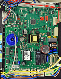
Disconnect connector CN8 from the main PCB
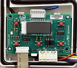
Disconnect connector CN2 from the display PCB
Disconnect connector CN2 from the display PCB
Measurement:
Measure the resistance of each of the wires in the display PCB harness. All 12 wires must be checked.
Expect short circuit on each test.
Also visually inspect the harness for any signs of damaged insulation and good general condition.
Note:
With both ends of the connector orientated the same way the pins on each connector correspond, i.e. top left on one end corresponds with top left on the opposite end of the harness (as illustrated with the red arrows)


Isolate as per TOPs P4
and refit as necessary