Set Appliance State:
| Isolate Mains Power to appliance as per TOPs P4 |
Set Multimeter to Resistance 
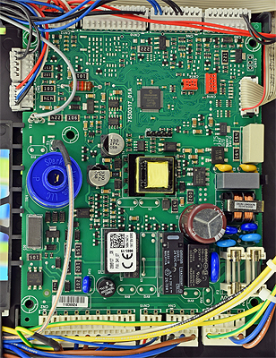
Remove connector CN2 from the main PCB
Remove the connection from the pump assembly
Remove the connection from the pump assembly
Measurement:
Test 1:
Measure the resistance between Pin 7 (Blue) on CN2 to the corresponding pin at the pump connector (refer to picture).
Expect continuity (zero resistance).
Test 2:
Measure the resistance between Pin 8 (Brown) on CN2 to the corresponding pin at the pump connector (refer to picture).
Expect continuity (zero resistance).
Also inspect the condition of the harness visually for general condition and any signs of damaged insulation.


Isolate as per TOPs P4
and refit as necessary