Set Appliance State:
| Isolate Mains Power to appliance as per TOPs P4 |
Set Multimeter to Resistance 
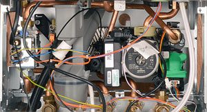
Disconnect the inline connector in the lead to the turbine
Disconnect the 20 way connector from the PCB
Disconnect the 20 way connector from the PCB
Measurement:
Check the turbine harness leads for continuity.
Measure between the ends of the disconnected inline connector to the grey, white and black leads in turn at terminals 12, 13 and 14 respectively of the disconnected connector at the PCB end.
Check the general lead condition.
Note:
The colours of the wires may vary but the terminal positions will remain the same.


Isolate as per TOPs P4
and refit as necessary