Set Appliance State:
| Isolate Mains Power to appliance as per TOPs P4 |
Set Multimeter to Resistance 
Remove signal control connector from fan assembly
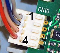
Slightly move connector CN10 on the PCB to exposed its
connections, ensure connector is still in contact with PCB
Slightly move connector CN10 on the PCB to exposed its
connections, ensure connector is still in contact with PCB
Measurement:
Measure the resistance (continuity) across the fan signal harness.
Expected resistance is continuity (zero resistance) across each wire of the harness.
Note.
Be aware that wiring swaps around on connectors & ensure a good connection is made during resistance tests or misdiagnosis will occur.
Expected resistance is continuity (zero resistance) across each wire of the harness.
Note.
Be aware that wiring swaps around on connectors & ensure a good connection is made during resistance tests or misdiagnosis will occur.


Isolate as per TOPs P4
and refit as necessary