Set Appliance State:
| Isolate Mains Power to appliance as per TOPs P4 |
Set Multimeter to Resistance 
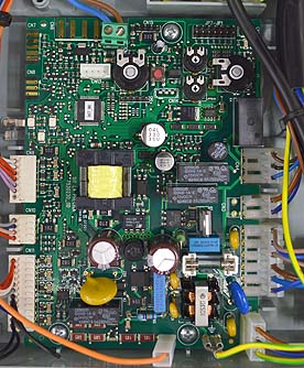
Remove connector CN2 from the PCB & electrical connector at gas valve
Measurement:
Measure the resistance (continuity) across the gas valve harness leads.
Connections are;
CN2 pins 5 & 6 to the corresponding connection at the gas valve connector, see table.
Expected resistance is continuity (zero resistance) across each wire of the harness.
Connections are;
CN2 pins 5 & 6 to the corresponding connection at the gas valve connector, see table.
Expected resistance is continuity (zero resistance) across each wire of the harness.


Isolate as per TOPs P4
and refit as necessary