Set Appliance State:
| Isolate Mains Power to appliance as per TOPs P4 |
Set Multimeter to AC Voltage 
Turn Hot Water Tap On
Remove lower facia panel
Selector switch in DHW position
Selector switch in DHW position
| WARNING! - Mains voltage is expected during test follow TOPs P4 live testing procedure |
Measurement:
Allow fan to run and boiler to commence its ignition sequence.
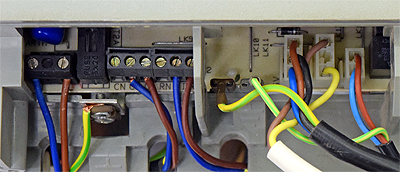
Measure voltage between brown wire (marked GV)
on connector block X5 and neutral (marked N)
on connector block X1.
Both connector blocks are situated at the bottom of the PCB.
Note:
Voltage will only be present for approximately ten seconds during ignition sequence then lockout will occur.
This can be reset by turning the mains power supply to the appliance OFF and ON again.


Isolate as per TOPs P4
and refit as necessary