G.C. Number 47 241 05
Warning - Important Notice:
The information contained within this application is for the use by and guidance of engineers, who have been trained in gas installation and/or gas service practice. Individuals must apply safe working practices in accordance with their training, while taking due regard of company procedures, when undertaking any type of work.
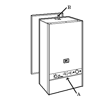
Case removal
Pull off the 3 control knobs located on the control panel (A).
Remove the 2 fixing screws from the control panel (A) and the 2 retaining nuts (Igniter and pilot off).
Remove the top clip retaining screw (B).
Unclip the two retaining clips located at the top and bottom of the case.
Carefully pull forward the case and remove.
To access the heat exchanger and the burner assembly remove the 5 screws securing the combustion chamber front panel top and bottom.
Swing the panel outwards and up from the bottom to disengage the location lugs.
Warning - Important Notice:
The information contained within this application is for the use by and guidance of engineers, who have been trained in gas installation and/or gas service practice. Individuals must apply safe working practices in accordance with their training, while taking due regard of company procedures, when undertaking any type of work.
Case removal
Pull off the 3 control knobs located on the control panel (A).
Remove the 2 fixing screws from the control panel (A) and the 2 retaining nuts (Igniter and pilot off).
Remove the top clip retaining screw (B).
Unclip the two retaining clips located at the top and bottom of the case.
Carefully pull forward the case and remove.
To access the heat exchanger and the burner assembly remove the 5 screws securing the combustion chamber front panel top and bottom.
Swing the panel outwards and up from the bottom to disengage the location lugs.
Isolate as per TOPs P4
and refit as necessary