Set Appliance State:
| Isolate Mains Power to appliance as per TOPs P4 |
Set Multimeter to DC Volts 
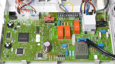
Gain access to PCB (use Insulation Mat as required)
| WARNING! - Mains voltage is expected during test follow TOPs P4 live testing procedure |
Measurement:
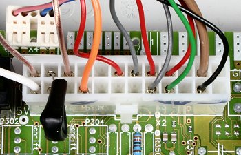
With no DHW demand, measure the voltage between
pin 9 (red wire) and pin 23 (black wire) at the
large multi-pin connector (X2) on the PCB.
Expect a voltage of approximately 5 volts DC.
Note:
There are two types of harness available for this boiler, the alternate harness will have 3 pink wires in place of the red, black and green wires. For testing purposes the function and the location of each wire is the same.

Isolate as per TOPs P4
and refit as necessary