Set Appliance State:
| Isolate Mains Power to appliance as per TOPs P4 |
Set Multimeter to DC Volts 
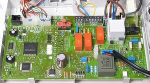
Gain access to PCB (use Insulation Mat as required)
Disconnect the display PCB from the front of the boiler fascia
Disconnect the display PCB from the front of the boiler fascia
| WARNING! - Mains voltage is expected during test follow TOPs P4 live testing procedure |
Measurement:
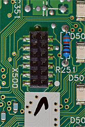
Using shrouded probes measure the voltage between
an Earth connection and connector X500.
With pin 1 being the top left, measure the voltages on the soldered points which should conform approximately to the table below:
an Earth connection and connector X500.
With pin 1 being the top left, measure the voltages on the soldered points which should conform approximately to the table below:
| Pin 1 = 3.5vdc | Pin 7 = 5vdc |
| Pin 2 = 3.5vdc | Pin 8 = 0vdc |
| Pin 3 = 3vdc | Pin 9 = 5vdc |
| Pin 4 = 5vdc | Pin 10 = 5vdc |
| Pin 5 = 5vdc | Pin 11 = 0vdc |
| Pin 6 = 5vdc | Pin 12 = 2.5vdc |


Isolate as per TOPs P4
and refit as necessary