Set Appliance State:
| Isolate Mains Power to appliance as per TOPs P4 |
Set Multimeter to DC Volts 
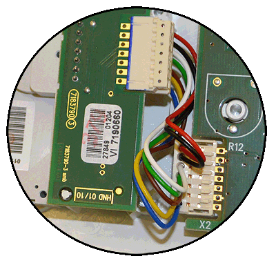
Gain access to the display PCB
Release the 2 clips on the facia and lower the panel
Ensure NO demand
Release the 2 clips on the facia and lower the panel
Ensure NO demand
| WARNING! - Mains voltage is expected during test follow TOPs P4 live testing procedure |
Measurement:
Test 1.
Measure the DC voltage between pin 5 (white) and
pin 7 (red) on connector X2 on the display PCB.
Expected voltage approximately 5V DC with no demand.
Test 2.
Set digital programmer to ON and perform Test 1 again.
Expected voltage should be approximately 0V DC with a demand.
Measure the DC voltage between pin 5 (white) and
pin 7 (red) on connector X2 on the display PCB.
Expected voltage approximately 5V DC with no demand.
Test 2.
Set digital programmer to ON and perform Test 1 again.
Expected voltage should be approximately 0V DC with a demand.


Isolate as per TOPs P4
and refit as necessary