Set Appliance State:
| Isolate Mains Power to appliance as per TOPs P4 |
Set Multimeter to Resistance 
Gain access to display PCB
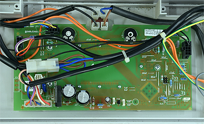
Disconnect X5 from the display PCB and the inline connector attached to it
Disconnect X5 from the display PCB and the inline connector attached to it
Measurement:
Test 1:
Measure the resistance between the pink and
right black wire (refer to picture) at the inline connector.
Resistance should be approximately 33Ω, plus the resistance of meter test leads.
Measure the resistance between the white wire to a suitable earth point.
Resistance should be greater than 1MΩ (or O.L.)
Test 2:
Measure the resistance between pin 3 (brown) and pin 4 (dark blue) on X5.
Resistance should be approximately 0.5Ω, plus the resistance of meter test leads.
Measure the resistance between pin 3 (brown) to a suitable earth point.
Resistance should be greater than 1MΩ (or O.L.)


Isolate as per TOPs P4
and refit as necessary