Set Appliance State:
| Isolate Mains Power to appliance as per TOPs P4 |
Set Multimeter to Resistance 
Remove electrode cover (2x screws) then
inner combustion cover (5x screws)
Disconnect inline connector to flame detection lead
inner combustion cover (5x screws)
Disconnect inline connector to flame detection lead
Measurement:
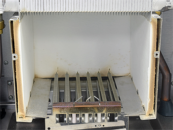
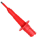
Check the detection electrode is in good condition and correctly positioned across the burner as in the picture.
Check that the gap between the burner
and the electrode is approximately 4mm.
Inspect the ceramic for any cracks or damage.
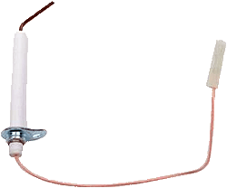
Check for continuity (zero resistance) between the
tip of the detection electrode to the connector and
that the lead is in good condition throughout.
Note:
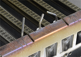
Electrode shown removed for clarity
but can be left in situ for test.
Check that the gap between the burner
and the electrode is approximately 4mm.
Inspect the ceramic for any cracks or damage.
Check for continuity (zero resistance) between the
tip of the detection electrode to the connector and
that the lead is in good condition throughout.
Note:
Electrode shown removed for clarity
but can be left in situ for test.


Isolate as per TOPs P4
and refit as necessary