Set Appliance State:
| Isolate Mains Power to appliance as per TOPs P4 |
Set Multimeter to Resistance 
Remove connector X11 from the PCB
Remove the AC fan connector (3 wire) from the fan assembly
Remove the AC fan connector (3 wire) from the fan assembly
Measurement:
Measure the resistance between each of the wires in the harness as below:
Brown wire on connector X11 to brown wire on the fan connector.
Blue wire on connector X11 to blue wire on the fan connector.
Earth wire on connector X11 to earth wire on the fan connector.
Expect continuity / zero resistance on each test.
Also visually inspect the condition of the harness.
Brown wire on connector X11 to brown wire on the fan connector.
Blue wire on connector X11 to blue wire on the fan connector.
Earth wire on connector X11 to earth wire on the fan connector.
Expect continuity / zero resistance on each test.
Also visually inspect the condition of the harness.
 fan ac connector pcb.gif)
 fan ac connector.gif)
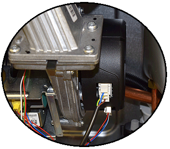
 pcb in situ.gif)

Isolate as per TOPs P4
and refit as necessary