Set Appliance State:
| Isolate Mains Power to appliance as per TOPs P4 |
Set Multimeter to Resistance 
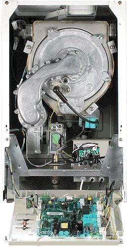
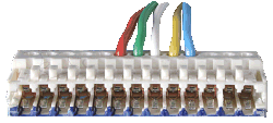
Remove the fan loom from the PCB (J4) and the fan
Measurement:
Check the fan loom for continuity and general condition.
Note:
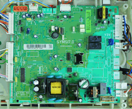
Some models may have been fitted with a DC supply box to control the fan. Be sure to test for continuity on all wires between the connector on the top of this unit and the fan and J4 on the main PCB.
Alternatively a model previously fitted with DC supply box may have had an updated PCB fitted. in this case you will find the fan loom will be connected via a Mod card (as shown) visually inspect this board and check continuity between here and fan and main PCB.
Note:
Some models may have been fitted with a DC supply box to control the fan. Be sure to test for continuity on all wires between the connector on the top of this unit and the fan and J4 on the main PCB.
Alternatively a model previously fitted with DC supply box may have had an updated PCB fitted. in this case you will find the fan loom will be connected via a Mod card (as shown) visually inspect this board and check continuity between here and fan and main PCB.
 in situ 2.gif)


Isolate as per TOPs P4
and refit as necessary