Set Appliance State:
| Isolate Mains Power to appliance as per TOPs P4 |
Set Multimeter to Resistance 
Disconnect connector J7 from the control PCB
Measurement:
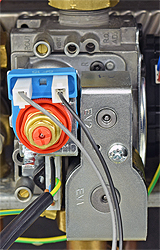
Inspect the condition of the harness between the gas valve modureg and the PCB.
Check for continuity between the grey wire (pin 1) at J7 connector to the grey wire at the modureg.
Check for continuity between the black wire (pin 2) at J7 connector to the black wire at the modureg.
Check for continuity between the grey wire (pin 1) at J7 connector to the grey wire at the modureg.
Check for continuity between the black wire (pin 2) at J7 connector to the black wire at the modureg.


Isolate as per TOPs P4
and refit as necessary