Set Appliance State:
| Isolate Mains Power to appliance as per TOPs P4 |
Set Multimeter to DC Volts 
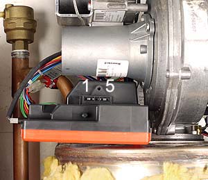
Remove ignition PCB from gas valve, place under fan assembly so gas valve connection is facing the front of boiler
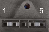
Multimeter probe required for this test is the thin long spike
Note: Do not push probe fully into PCB connector
Multimeter probe required for this test is the thin long spike
Note: Do not push probe fully into PCB connector
| WARNING! - Mains voltage is expected during test follow TOPs P4 live testing procedure |
Measurement:
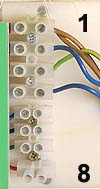
Test 1. With no demand present measure for DC voltage across terminal 2 (ignition PCB) and terminal 2 (blue) main terminal block.
Expected voltage approximately 133 - 137 Vdc.
Apply DHW demand, 7 seconds after fan has started the voltage should reduce to approximately 118 Vdc.
Test 2. With no demand present measure for DC voltage across terminal 5 (ignition PCB) and terminal 2 (blue) main terminal block.
Expected voltage approximately 133 - 137 Vdc.
Apply DHW demand, 7 seconds after fan has started the voltage
should reduce to approximately 127 Vdc.
Expected voltage approximately 133 - 137 Vdc.
Apply DHW demand, 7 seconds after fan has started the voltage should reduce to approximately 118 Vdc.
Test 2. With no demand present measure for DC voltage across terminal 5 (ignition PCB) and terminal 2 (blue) main terminal block.
Expected voltage approximately 133 - 137 Vdc.
Apply DHW demand, 7 seconds after fan has started the voltage
should reduce to approximately 127 Vdc.


Isolate as per TOPs P4
and refit as necessary