Set Appliance State:
| Isolate Mains Power to appliance as per TOPs P4 |
Set Multimeter to Resistance 
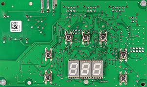
Remove front facia from display PCB, refit PCB to boiler frame
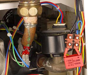
Remove connector to system pressure sensor
Remove connector to system pressure sensor
Measurement:
Test 1. Measure for continuity (short circuit) between
pin 1 (X2 PCB) and yellow lead removed connector.
Test 2. Measure for continuity (short circuit) between
pin 2 (X2 PCB) and red lead removed connector.
Test 3. Measure for continuity (short circuit) between
pin 3 (X2 PCB) and blue lead removed connector.
Note.
Due to the small size of the connectors used on this appliance,
harness checks are carried out from PCB connections.


Isolate as per TOPs P4
and refit as necessary