Set Appliance State:
| Isolate Mains Power to appliance as per TOPs P4 |
Set Multimeter to Resistance 
Remove electrical connector to flow sensor
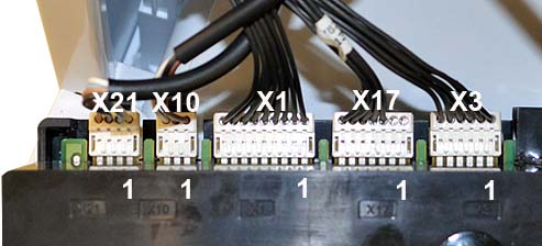
Remove connector X17 from PCB
Remove connector X17 from PCB
Measurement:
Test 1.
Measure the resistance across X17 connector, pins 5,6 & 7
to a suitable earth connection
Expected resistance greater than 1 Mohm, each pin to earth.
Test 2.
Measure the resistance across pin 6 connector X17 to pin 5
of the same connector.
Repeat test for pin 5 to pin 7.
Expected resistance greater than 1 Mohm.
Note.
1. PCB connector numbers can be found on the plastic moulding surrounding the board.
2. Ensure a good connection is made or misdiagnosis will occur.


Isolate as per TOPs P4
and refit as necessary