Set Appliance State:
| Isolate Mains Power to appliance as per TOPs P4 |
Set Multimeter to Resistance 
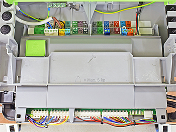
Gain access to PCB (use Insulation Mat as required)
Disconnect LV1 from the PCB
Disconnect LV1 from the PCB
Measurement:
Test 1:
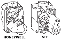
Measure the resistance between pin 1 (red) and pin 2 (black) at connector LV1.
Resistance depends on which gas valve is fitted:
Honeywell valve: Resistance should be approximately 115 Ohms.
SIT valve: Resistance should be approximately 70 Ohms.
Test 2:
Measure the resistance from pin 1 (red) to a suitable earth point.
Resistance should be greater than 1M Ohm (or O.L on meter).
Is the resistance measured as expected?
Note:
Connector may differ slightly in appearance but this does not affect the test.


Isolate as per TOPs P4
and refit as necessary