Set Appliance State:
| Isolate Mains Power to appliance as per TOPs P4 |
Set Multimeter to Resistance 
Remove the DC pump connector from the pump
Measurement:
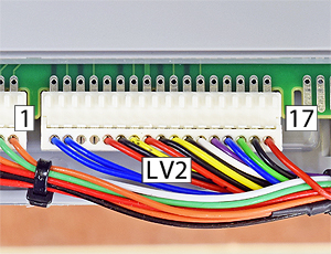
Measure the resistance between each of the wires at the pump connector to the corresponding wire at the PCB connector LV2 (pin 11-13)
Expect continuity / zero resistance on each of the wires in the harness.
Also visually inspect the condition of the harness and its connectors.
Are the resistances as expected and is the harness in good condition?
Note:
Test in the end of the pump DC connector where it pushes onto the pump terminals, DO NOT try and use the small silver parts in the cut-outs on the side of the connector as pressing test probes onto them damages the harness (irreparably in most cases).


Isolate as per TOPs P4
and refit as necessary