Set Appliance State:
| Isolate Mains Power to appliance as per TOPs P4 |
Set Multimeter to Resistance 
Remove connector CN4 from the main PCB
Remove the connector from the diverter valve
Remove the connector from the diverter valve
Measurement:
Measure the resistance between each of the pins on CN4 and the diverter valve connector as listed below:
Expect continuity on each test.
Also inspect the condition of the harness visually checking for any damaged insulation.
Note:
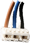
Each pin on the PCB connector is numbered.
| Connector CN4 | Diverter valve Connector | Pin 1 (Black) | Pin 1 (Black) |
| Pin 2 (Blue) | Pin 2 (Blue) |
| Pin 3 (brown) | Pin 3 (Brown) |
Expect continuity on each test.
Also inspect the condition of the harness visually checking for any damaged insulation.
Note:
Each pin on the PCB connector is numbered.
.gif)
.gif)


Isolate as per TOPs P4
and refit as necessary