Set Appliance State:
| Isolate Mains Power to appliance as per TOPs P4 |
Set Multimeter to Resistance 
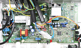
Remove connector X6A from the PCB
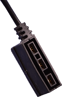
Remove the connector from the diverter valve motor
Remove the connector from the diverter valve motor
Measurement:
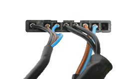
Measure the resistance of each of the wires in the diverter valve harness.
Pin 1 on X6A to pin 1 on the diverter connector.
Pin 2 on X6A to pin 3 on the diverter connector.
Pin 3 on X6A to pin 2 on the diverter connector.
Expect short circuit or zero resistance on each wire.
Also visually inspect the condition of the harness.
Are the resistances as expected and the harness in good condition?

Isolate as per TOPs P4
and refit as necessary