Set Appliance State:
| Isolate Mains Power to appliance as per TOPs P4 |
Set Multimeter to Resistance 
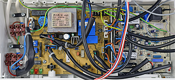
Disconnect connector J2 from the control PCB
Measurement:
Test 1:
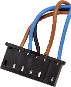
Measure the resistance between the two blue wires on J2.
Resistance should be short circuit (zero resistance).
Test 2:
Measure the resistance between the two brown wires and the black wire to one of the two neutral (blue) wires on J2.
Pin 2 (brown) to neutral: Approx. 45 Ohms
Pin 4 (black) to neutral: Greater than 1M Ohm
Pin 5 (brown) to neutral: Greater than 1M Ohm.
Test 3:
Measure the resistance between the two brown wires and the black wire to a suitable earth point.
Pin 2 (brown) to earth: Greater than 1M Ohm
Pin 4 (black) to earth: Greater than 1M Ohm
Pin 5 (brown) to earth: Greater than 1M Ohm.


Isolate as per TOPs P4
and refit as necessary