Set Appliance State:
| Isolate Mains Power to appliance as per TOPs P4 |
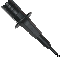
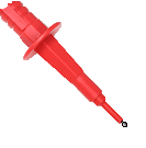
Set Multimeter to Resistance 
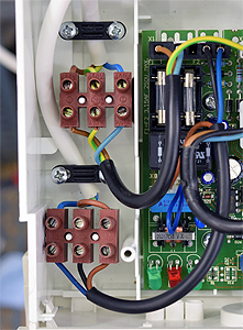
Disconnect connector X1 from the PCB
Disconnect connector X8 from the PCB (connector X5 on white PCB)
Disconnect connector X8 from the PCB (connector X5 on white PCB)
Measurement:
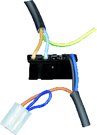
Check the condition of the harness between the external controls terminal block and connectors X1 / X8 at the PCB.
Check for continuity between:
Brown on X8 to brown on terminal block,
Black on X1 to black on terminal block,
Dark Blue on X1 to dark blue on terminal block.
Note:
If a white PCB is fitted X8 is instead called X5, (X8 on the white PCB is an unused plug to the right of the PCB).
Check for continuity between:
Brown on X8 to brown on terminal block,
Black on X1 to black on terminal block,
Dark Blue on X1 to dark blue on terminal block.
Note:
If a white PCB is fitted X8 is instead called X5, (X8 on the white PCB is an unused plug to the right of the PCB).

Isolate as per TOPs P4
and refit as necessary