Set Appliance State:
| Isolate Mains Power to appliance as per TOPs P4 |
Set Multimeter to DC Volts 
Turn Hot Water Tap On
Gain access to PCB (use Insulation Mat as required)
| WARNING! - Mains voltage is expected during test follow TOPs P4 live testing procedure |
Measurement:
Reset appliance as necessary.
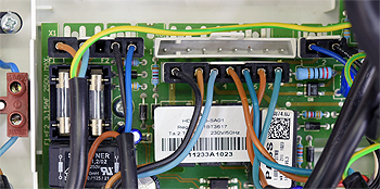
Once the appliance begins the sparking stage of its ignition sequence, measure the voltage between pins 6 and 7 (brown and blue wires) on X6b connector at the PCB.
Approximately 210V DC expected.
Note:
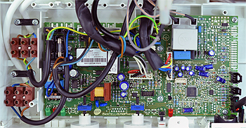
If a white board is fitted connector is in same location but is called X6 instead of X6b.
Once the appliance begins the sparking stage of its ignition sequence, measure the voltage between pins 6 and 7 (brown and blue wires) on X6b connector at the PCB.
Approximately 210V DC expected.
Note:
If a white board is fitted connector is in same location but is called X6 instead of X6b.


Isolate as per TOPs P4
and refit as necessary