Set Appliance State:
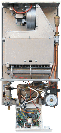
| Isolate Mains Power to appliance as per TOPs P4 |
Set Multimeter to Resistance 
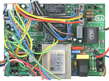
Remove plastic cover from the PCB
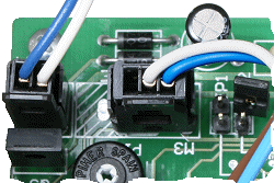
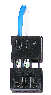
Remove air pressure switch connector from M3 on the PCB
Remove air pressure switch connector from M3 on the PCB
Measurement:
Note the operating pressure indicated on the pressure switch.
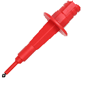
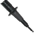
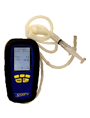
Connect the air pressure switch charge kit to +ve connection on the air pressure switch.
Increase the pressure via the syringe to that indicated on the pressure switch. Continuity should then be measured across the blue and white wires.
Note:
If continuity is not obtained it is permissible to increase the pressure by 50%.
100 Pascals = 1mbar / 50 Pascals = 0.5mbar


Isolate as per TOPs P4
and refit as necessary