Set Appliance State:
| Isolate Mains Power to appliance as per TOPs P4 |
Set Multimeter to DC Volts 
CH Demand
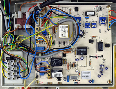
Gain access to PCB (use Insulation Mat as required)
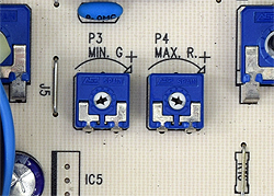
Turn potentiometer marked P4 MAX fully anticlockwise
Turn potentiometer marked P4 MAX fully anticlockwise
| WARNING! - Mains voltage is expected during test follow TOPs P4 live testing procedure |
Measurement:
Once burner has established (sparking ceased)
burner should drop to minimum rate.
Test 1:
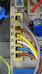
Measure the voltage between connections 21 (grey wire)
and 22 (Brown wire) at connector M4 on the PCB.
Voltage may vary slightly but should be less than 30V DC.
Test 2:
Measure the voltage between connections 23 (yellow wire)
and 24 (white wire) at connector M4 on the PCB.
Voltage may vary slightly but should be less than 90V DC.
Turn P4 back fully clockwise once test is complete.
Note: Manufacturer instructions provide a different method of measuring minimum rate.
This test is preferred by the lab as it reduces the chance of electrical contact.
burner should drop to minimum rate.
Test 1:
Measure the voltage between connections 21 (grey wire)
and 22 (Brown wire) at connector M4 on the PCB.
Voltage may vary slightly but should be less than 30V DC.
Test 2:
Measure the voltage between connections 23 (yellow wire)
and 24 (white wire) at connector M4 on the PCB.
Voltage may vary slightly but should be less than 90V DC.
Turn P4 back fully clockwise once test is complete.
Note: Manufacturer instructions provide a different method of measuring minimum rate.
This test is preferred by the lab as it reduces the chance of electrical contact.


Isolate as per TOPs P4
and refit as necessary