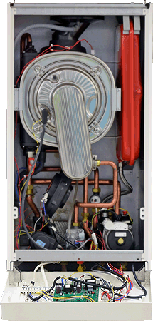
Set Appliance State:
| Isolate Mains Power to appliance as per TOPs P4 |
Set Multimeter to Resistance 
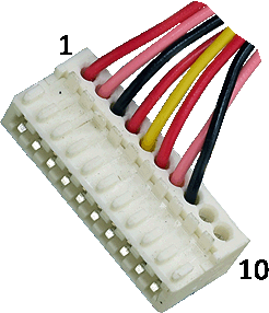
Disconnect connector X7 from the PCB
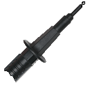
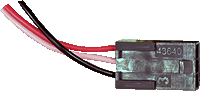
Disconnect inline connector to flow switch
Disconnect inline connector to flow switch
Measurement:
Check for continuity (zero resistance) between the wires running from the flow switch to pins 6 (red), 7 (pink), and 8 (black) at connector X7.
Inspect the harness and plugs for good overall condition.
Inspect the harness and plugs for good overall condition.


Isolate as per TOPs P4
and refit as necessary