Set Appliance State:
| Isolate Mains Power to appliance as per TOPs P4 |
Set Multimeter to Resistance 
Gain access to PCB (use Insulation Mat as required)
Disconnect rectification lead from electrode assembly
Disconnect rectification lead from electrode assembly
Measurement:
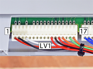
Measure the resistance between the end of the rectification lead to pin 4 (white) at LV1 on the PCB.
Expect continuity / zero resistance.
Inspect lead and connector for good overall condition.
Are the checks satisfactory?
Note:
Connector may differ slightly in appearance but this does not affect the test.
Expect continuity / zero resistance.
Inspect lead and connector for good overall condition.
Are the checks satisfactory?
Note:
Connector may differ slightly in appearance but this does not affect the test.


Isolate as per TOPs P4
and refit as necessary