Set Appliance State:
| Isolate Mains Power to appliance as per TOPs P4 |
Set Multimeter to DC Volts 
Turn Hot Water Tap On
Remove the gas valve connectors from the gas valve and make safe
Gain access to PCB (use insulation Mat as required)
Gain access to PCB (use insulation Mat as required)
| WARNING! - Mains voltage is expected during test follow TOPs P4 live testing procedure |
Measurement:
Reset appliance if necessary (press and hold reset button for 5 seconds, then release).
Test 1:
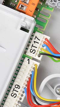
Allow ignition sequence to commence and measure the DC voltage between pin 1 on connector ST9 and the DC Neutral terminal.
Approximately 27 vdc should be present which reduces to approximately 0 vdc during the sparking stage of the ignition sequence before returning to approximately 27 vdc when sparking ceases.
Test 2:
Repeat above test for pin 3 of ST9 - the voltage should behave in the same way.
Notes:
1. Ensure a good connection is made and take care not to short the connections.
2. Lockout will occur after 5 attempts to ignite, reset as required until tests are complete.
Test 1:
Allow ignition sequence to commence and measure the DC voltage between pin 1 on connector ST9 and the DC Neutral terminal.
Approximately 27 vdc should be present which reduces to approximately 0 vdc during the sparking stage of the ignition sequence before returning to approximately 27 vdc when sparking ceases.
Test 2:
Repeat above test for pin 3 of ST9 - the voltage should behave in the same way.
Notes:
1. Ensure a good connection is made and take care not to short the connections.
2. Lockout will occur after 5 attempts to ignite, reset as required until tests are complete.


Isolate as per TOPs P4
and refit as necessary