Set Appliance State:
| Isolate Mains Power to appliance as per TOPs P4 |
Set Multimeter to Resistance 
Break the inline connector in the turbine lead
Remove ST9 connector from the PCB
If available use the Worcester test PCB to assist resistance test
Remove ST9 connector from the PCB
If available use the Worcester test PCB to assist resistance test
Measurement:
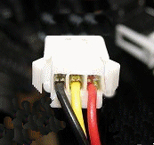
Check continuity of each wire in turn of the turbine harness
and inspect it's general condition.
Test 1. Check continuity between pin12 (black) ST9 and black wire inline connector.
Test 2. Check continuity between pin13 (yellow) ST9 and yellow wire inline connector.
Test 3. Check continuity between pin14 (red) ST9 and red wire inline connector.
and inspect it's general condition.
Test 1. Check continuity between pin12 (black) ST9 and black wire inline connector.
Test 2. Check continuity between pin13 (yellow) ST9 and yellow wire inline connector.
Test 3. Check continuity between pin14 (red) ST9 and red wire inline connector.


Isolate as per TOPs P4
and refit as necessary