Set Appliance State:
| Isolate Mains Power to appliance as per TOPs P4 |
Set Multimeter to Resistance 
Remove control box cover if necessary
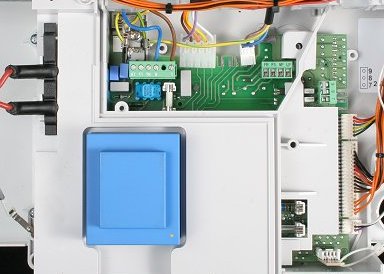
Remove the 20 way connector (ST9) from the right hand side of the PCB
If available use the Worcester test PCB to assist resistance test
Remove the 20 way connector (ST9) from the right hand side of the PCB
If available use the Worcester test PCB to assist resistance test
Measurement:
Measure the resistance across the two red wires terminals
7 and 8 counting left to right on the 20 way connector.
Expected resistance continuity (short circuit).
Note:
Colours may vary from those
shown but terminal positions
will remain the same.
7 and 8 counting left to right on the 20 way connector.
Expected resistance continuity (short circuit).
Note:
Colours may vary from those
shown but terminal positions
will remain the same.

Isolate as per TOPs P4
and refit as necessary