Set Appliance State:
| Isolate Mains Power to appliance as per TOPs P4 |
Set Multimeter to Resistance 
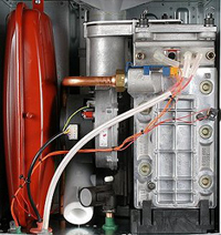
Remove the blue lead from the flame sense electrode and unplug the large 20 way connector (ST9) from the right hand side of the PCB
If available use the Worcester test PCB to assist resistance test
If available use the Worcester test PCB to assist resistance test
Measurement:
Measure across the end disconnected from the electrode to the blue lead at terminal 8 of the disconnected connector at the PCB end.
Check the general lead condition.
Note:
Colour of wires may vary but the terminal position will remain the same.
Check the general lead condition.
Note:
Colour of wires may vary but the terminal position will remain the same.


Isolate as per TOPs P4
and refit as necessary