Set Appliance State:
| Isolate Mains Power to appliance as per TOPs P4 |
Set Multimeter to Resistance 
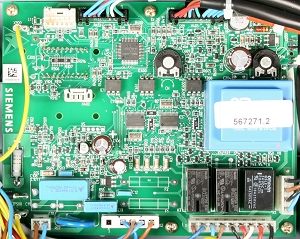
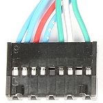
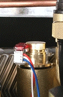
Remove connector X400 from PCB and connector from the hall sensor on the flow switch
Measurement:
Measure the resistance of the red (3) blue (4) and white (7) wires from the PCB connector X400 to the corresponding wire on the hall sensor connector.
Expect continuity / zero resistance on each of the wires.
Also visually check the condition of each of the wires in the harness.
Are the resistances as expected and is the harness in good condition?
Expect continuity / zero resistance on each of the wires.
Also visually check the condition of each of the wires in the harness.
Are the resistances as expected and is the harness in good condition?


Isolate as per TOPs P4
and refit as necessary