Set Appliance State:
| Isolate Mains Power to appliance as per TOPs P4 |
Set Multimeter to DC Volts 
Turn Hot Water Tap On
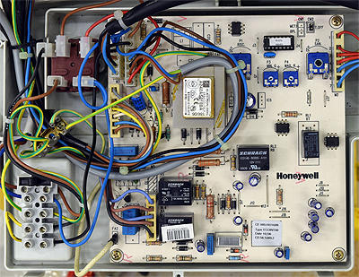
Gain access to PCB (use Insulation Mat as required)
Selector switch to DHW position
CH temperature selector to minimum
DHW temperature selector to maximum
Selector switch to DHW position
CH temperature selector to minimum
DHW temperature selector to maximum
| WARNING! - Mains voltage is expected during test follow TOPs P4 live testing procedure |
Measurement:
Allow fan to run and ignition sequence to commence
then at the sparking stage of the ignition sequence:
Test 1:
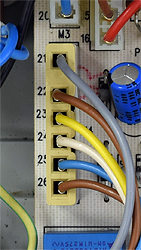
Measure the voltage between connections 21 (grey wire)
and 22 (Brown wire) at connector M4 on the PCB.
Voltage may vary slightly but should be at least 50V DC.
Test 2:
Measure the voltage between connections 23 (yellow wire)
and 24 (white wire) at connector M4 on the PCB.
Voltage may vary slightly but should be at least 120V DC.
Note:
Voltage will only be present for approximately 10 seconds, boiler may go to lockout. Reset appliance and retest as necessary.
then at the sparking stage of the ignition sequence:
Test 1:
Measure the voltage between connections 21 (grey wire)
and 22 (Brown wire) at connector M4 on the PCB.
Voltage may vary slightly but should be at least 50V DC.
Test 2:
Measure the voltage between connections 23 (yellow wire)
and 24 (white wire) at connector M4 on the PCB.
Voltage may vary slightly but should be at least 120V DC.
Note:
Voltage will only be present for approximately 10 seconds, boiler may go to lockout. Reset appliance and retest as necessary.


Isolate as per TOPs P4
and refit as necessary