Set Appliance State:
| Isolate Mains Power to appliance as per TOPs P4 |
Set Multimeter to Resistance 
Remove connector CN9 from the PCB
Measurement:
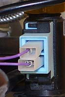
Measure the resistance (continuity) across the flow sensor harness leads.
Connections are;
CN9 pins 6 & 5 to the corresponding connection on the DHW flow sensor.
Expected resistance is continuity (zero resistance) across each wire of the harness.
Connections are;
CN9 pins 6 & 5 to the corresponding connection on the DHW flow sensor.
Expected resistance is continuity (zero resistance) across each wire of the harness.


Isolate as per TOPs P4
and refit as necessary