Set Appliance State:
| Isolate Mains Power to appliance as per TOPs P4 |
Set Multimeter to Resistance 
Remove connector CN2 from the PCB
Measurement:
Measure the resistance (continuity) across the pump harness leads:
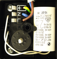
Connections are;
CN2 pin 4 (brown) to the connection marked L at the pump wiring.
CN2 pin 1 (blue) to the connection marked N at the pump wiring.
Expected resistance is continuity (zero resistance) across each wire of the harness.
Inspect harness and connectors for good overall condition.
Connections are;
CN2 pin 4 (brown) to the connection marked L at the pump wiring.
CN2 pin 1 (blue) to the connection marked N at the pump wiring.
Expected resistance is continuity (zero resistance) across each wire of the harness.
Inspect harness and connectors for good overall condition.


Isolate as per TOPs P4
and refit as necessary