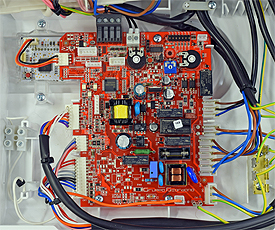
Set Appliance State:
| Isolate Mains Power to appliance as per TOPs P4 |
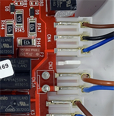
Set Multimeter to Resistance 
Remove electrical connector from diverter valve (DV) actuator
Measurement:
Measure the resistance (continuity) across the DV actuator harness leads.
Connections are;
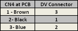
CN4 pins 1,2 & 3 to the corresponding connection at the DV actuator connector, see table;
Expected resistance is continuity (zero resistance)
across each wire of the harness.
Note.
Ensure a good connection is made during resistance
tests or misdiagnosis will occur.
Connections are;
CN4 pins 1,2 & 3 to the corresponding connection at the DV actuator connector, see table;
Expected resistance is continuity (zero resistance)
across each wire of the harness.
Note.
Ensure a good connection is made during resistance
tests or misdiagnosis will occur.


Isolate as per TOPs P4
and refit as necessary