Set Appliance State:
| Isolate Mains Power to appliance as per TOPs P4 |
Set Multimeter to Resistance 
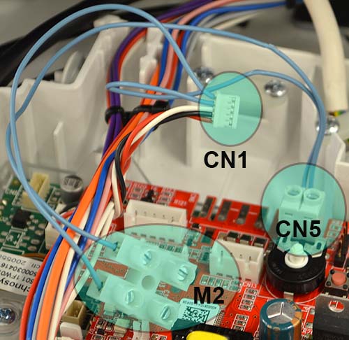
Remove connector CN1 from the programmer PCB
Measurement:
Measure the resistance (continuity) across each wire of the programmer harness (blue wires) which run between CN5 (PCB), CN1 (programmer PCB) & M2 terminal strip.
Note.
The colour of the wiring harness may change but test remains the same.
Note.
The colour of the wiring harness may change but test remains the same.


Isolate as per TOPs P4
and refit as necessary