Set Appliance State:
| Isolate Mains Power to appliance as per TOPs P4 |
Set Multimeter to Resistance 
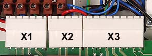
Remove X2 from the PCB and the connector at the diverter valve
Disengage Diverter head to facilitate connector removal
Disengage Diverter head to facilitate connector removal
Measurement:
Measure the resistance of each wire of the harness.
The resistance should conform to the table below:
Note.
For instructions to refit diverter valve actuator CLICK HERE
The resistance should conform to the table below:
| Wire | Resistance in Ohms | Blue - Blue | Continuity (zero resistance) |
| Brown - Brown | Continuity (zero resistance) |
| Black - Black | Continuity (zero resistance) |
| Blue - Blue | Continuity (zero resistance) |
Note.
For instructions to refit diverter valve actuator CLICK HERE


Isolate as per TOPs P4
and refit as necessary