Set Appliance State:
| Isolate Mains Power to appliance as per TOPs P4 |
Set Multimeter to Resistance 
Disconnect connector from flow switch
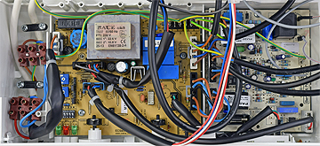
Disconnect connector X6 from the control PCB
Disconnect connector X6 from the control PCB
Measurement:
Check for continuity of the harness between the flow switch and the control PCB:
Red to Red (pin 4 on J6).
White to White (pin 5 on J6).
Blue to Blue (pin 6 on J6).
Also inspect the overall
condition of the harness.
Red to Red (pin 4 on J6).
White to White (pin 5 on J6).
Blue to Blue (pin 6 on J6).
Also inspect the overall
condition of the harness.


Isolate as per TOPs P4
and refit as necessary