Set Appliance State:
| Isolate Mains Power to appliance as per TOPs P4 |
Set Multimeter to Resistance 
Disconnect connector marked X1 from the PCB
Measurement:
Test 1:
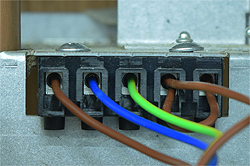
Check for continuity (zero resistance) between the brown wire marked L on X1 and the brown wire marked L2 on the mains inlet connector.
Test 2:
Check for continuity between the blue wire marked N on X1 and the blue wire marked N on the mains inlet connector.
Also carry out a visual inspection of the harness
between the mains inlet connector and the PCB.


Isolate as per TOPs P4
and refit as necessary