Set Appliance State:
| Isolate Mains Power to appliance as per TOPs P4 |
Set Multimeter to Resistance 
Disconnect connector X6 from the PCB
Measurement:
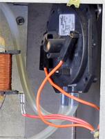
Note the operating pressure indicated on the pressure switch.
Connect the air pressure switch charge kit to
+ve connection on the air pressure switch,
disconnect the -ve connection.
Ensure the performance tester reads 0mb.
Increase the pressure via the syringe to that
indicated on the pressure switch. Continuity
should then be measured across the orange
wires marked 9 and 10 on X6 connector.
Notes:
100Pa (Pascals) = 1millibar
If continuity is not measured it is permissible
to increase the pressure by up to 50%
If continuity is measured keep air pressure switch
charge kit connected to air pressure switch.


Isolate as per TOPs P4
and refit as necessary