Set Appliance State:
| Isolate Mains Power to appliance as per TOPs P4 |
Set Multimeter to AC Volts 
Turn Hot Water Tap On
Disconnect lead from gas valve and make safe
Selector Switch in Hot Water Position
Selector Switch in Hot Water Position
| WARNING! - Mains voltage is expected during test follow TOPs P4 live testing procedure |
Measurement:
Reset appliance as necessary during tests.
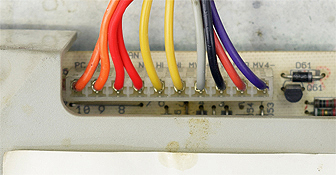
Test 1: During the sparking stage of the ignition sequence measure for voltage between the grey wire marked 4 on X6 at the PCB and a suitable earth point.
Expected voltage approximately 130V AC.
Test 2: During the sparking stage of the ignition sequence measure for voltage between the black wire marked 3 on X6 at the PCB and a suitable earth point.
Expected voltage approximately 120V AC.
Notes: There may be voltages present before or after the sparking stage of the ignition sequence but these voltages are not relevant to the tests.


Isolate as per TOPs P4
and refit as necessary