Set Appliance State:
| Isolate Mains Power to appliance as per TOPs P4 |
Set Multimeter to Resistance 
Gain access to PCB (use Insulation Mat as required)
Remove lower facia panel
Disconnect the connector X5 on the PCB (marked GV)
Remove lower facia panel
Disconnect the connector X5 on the PCB (marked GV)
Measurement:
Test 1:
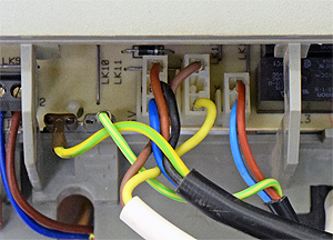
Measure the resistance across the black wire (connection 2) and blue wire (connection 3) on the disconnected connector, approximately 850 Ohms should be present.
Test 2:
Measure the resistance across the brown wire (connection 1) and blue wire (connection 3) on the disconnected connector, approximately 850 Ohms should be present.

Isolate as per TOPs P4
and refit as necessary