Set Appliance State:
| Isolate Mains Power to appliance as per TOPs P4 |
Set Multimeter to Resistance 
Gain access to PCB (use Insulation Mat as required)
Remove leads from DHW flow switch
Remove leads from DHW flow switch
Measurement:
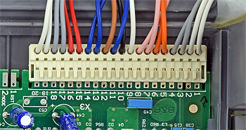
Measure the resistance between pins 7 and 8 at X3 to the corresponding wire at the DHW flow switch.
Expect continuity / zero resistance on each test.
Also visually inspect the condition of the harness and its connectors.
Expect continuity / zero resistance on each test.
Also visually inspect the condition of the harness and its connectors.


Isolate as per TOPs P4
and refit as necessary