Set Appliance State:
| Isolate Mains Power to appliance as per TOPs P4 |
Observation:
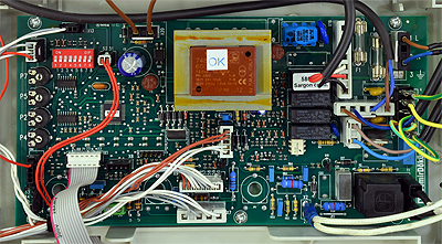
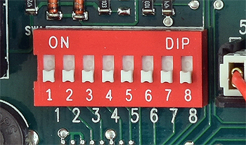
Confirm PCB dip switches are set correctly.
The first 6 dip switches for Heatline C24 / C28 are all set to OFF, unless
system has under floor heating or CH system has an external pump.
Switch 7 should be set to OFF for NG and ON for LPG
Switch 8 should be set to OFF for C24 and ON for C28.
Note:
1. Switch 1 Factory set to OFF position
2. Switch 2 Pump mode, OFF = normal mode, ON = pump only works when burner is on
3. Switch 3 45 second delay, OFF = 45 second delay re-ignition DHW demand to CH, ON = no delay
4. Switch 4 Factory set to OFF position
5. Switch 5 Integral pump, OFF = integral pump CH & DHW, ON = integral pump DHW only, CH external pump
6. Switch 6 Flow temperature, OFF = 90°C, ON = Max 50°C - Min 30°C (under floor heating)
7. Switch 7 NG = OFF, LPG = ON
8. Switch 8 Heatline C24 = OFF, Heatline C28 = ON