Set Appliance State:
| Isolate Mains Power to appliance as per TOPs P4 |
Set Multimeter to DC Volts 
Turn Hot Water Tap On
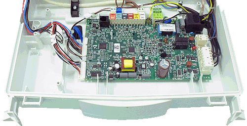
Gain access to PCB (use Insulation Mat as required)
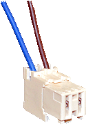
Remove gas valve connector from the PCB and make safe
Remove gas valve connector from the PCB and make safe
| WARNING! - Mains voltage is expected during test follow TOPs P4 live testing procedure |
Measurement:
Reset the appliance if required.
(Press reset button once then release)
Allow the fan to run and the ignition sequence to commence.
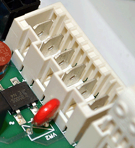
Measure for DC voltage between pin 4 on the main PCB where the gas valve connector was fitted to a suitable earth point.
Expected voltage approx. 230 VDC.
230 VDC should be present for 7 seconds, this will then be present again after approximately 7 seconds. This will be repeated 3 times before lockout occurs, reset as required until test is complete.
(Press reset button once then release)
Allow the fan to run and the ignition sequence to commence.
Measure for DC voltage between pin 4 on the main PCB where the gas valve connector was fitted to a suitable earth point.
Expected voltage approx. 230 VDC.
230 VDC should be present for 7 seconds, this will then be present again after approximately 7 seconds. This will be repeated 3 times before lockout occurs, reset as required until test is complete.


Isolate as per TOPs P4
and refit as necessary