Set Appliance State:
| Isolate Mains Power to appliance as per TOPs P4 |
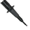
Set Multimeter to Resistance 
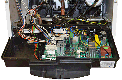
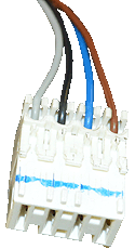
Remove connector CN10 from the PCB
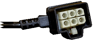
Disconnect the electrical connector from the pump assembly
Disconnect the electrical connector from the pump assembly
Measurement:
This test can be difficult to carry out with both connectors removed, therefore it is advisable to wedge the pump connector somewhere suitable for ease of testing.
Test 1.
Measure the resistance between pin 6 on the
pump connector and pin 2 on connector CN10.
Test 2.
Measure the resistance between pin 2 on the
pump connector and pin 3 on connector CN10.
Test 3.
Measure the resistance between pin 4 on the
pump connector and pin 1 on connector CN10.
Test 4.
Measure the resistance between pin 3 on the
pump connector and pin 4 on connector CN10.
Expect continuity / zero resistance on each test.
Also visually inspect the condition of the harness.


Isolate as per TOPs P4
and refit as necessary